DEWETRON systems are designed to help our customers make the world more predictable, efficient and safe. One of our strengths is our customized approach. This allows us to fulfill application-specific requirements with respect to the chassis, signal conditioning, software features and accessories.
- mehrAerospace & Defense
- mehrAutomotive Industry
- mehrEnergy & Power Analysis
- mehrManufacturing & Industrial
Choosing DEWETRON means having a partner by your side who accompanies you every step of the way. The high quality of DEWETRON’s R&D as well as the manufacturing of our products complies with the standards of ISO9001, ISO14001 and ISO17025.
Our Company
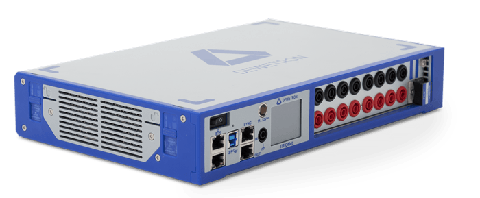
![NEX[DAQ] in a hand - small but powerful](https://www.dewetron.com/wp-content/uploads/2022/04/NEXDAQ-in-Hand.webp)